Extended Drawing Attributes
- As an expression of other drawing attributes
- As a result of ODBC queries
- As a combination of the above
<drawing attribute name> = <drawing attribute expression>The drawing attribute expression is basically a verbatim string where everything in a $(..) construct refers to the value of another drawing attribute, a configuration variable or an environment variable (in that order).
DBQUERY function
DBQUERY (<ODBC data source name>, <sql statement>)
PSDS 8.9 SI Example
PSDS 8.9 SI Example;proj
PSDS 8.9 SI Example;proj;none
Driver={Microsoft Access Driver (*.mdb, *.accdb)};Dbq=\\pluif7010reml\PSDS_Imperial\english.mdb;
Driver={Microsoft Access Driver (*.mdb, *.accdb)};Dbq=Z:\english.mdb;
Multi Row Results
DBQUERY will now return a comma separated list of values in case the query results in multiple rows. Please note that still only the first column will be listed.
For Example in the caseDBQUERY ($(IE_DSN2), Select code from CONN_DESC)
Hide Temporary Drawing Attributes
By adding the '@' in front of the drawing attribute definition, you can prevent it from displaying in the drawing attribute list in the isometric. The purpose is hide intermediate results that are not of interest.
@IE_DSN2=Driver={Microsoft Access Driver (*.mdb, *.accdb)};
Dbq=\\pluif7010reml\PSDS_Imperial\english.mdb;
a02 = DBQUERY ($(IE_DSN2), Select description from CONN_DESC where code='BR')
The result is IE_DSN2 is not shown in the drawing attributes. It
can however be referenced (without the '@') in the
textnodes.txt file.
DBQuery enhancement
An option is offered to add drawing attributes based on the most common value of a component attribute. This is particularly useful in cases of pipeline properties stored as component attributes.
- $(name) resolves to the value for drawing attribute named ”name"
- *(name) resolves to the most common value of the component attribute named ”name"
- Area = *(AREAID)
For AutoPLANT Modeler version 08.11.10.182 and earlier, the workspace for isometrics does not include the query and grid functionality. It can be added for now by changing the content of isoproj.cfg and adding 2 configuration files.
In the ProgramData\Bentley\Plant V8i\Bentley Plant V8i Projects\SAMPLE_IMPERIAL\Config\OpenPlant\Isometrics\isoproj.cfg file,
# Report defintion file IE_REPORTDEF = $(IE_CONF)report.def # Defines the file uses to define sort groups IE_REP_SORTGROUPS = $(IE_CONF)rep_sortgroups.txt # Grid definition file IE_GRID = $(IE_CONF)gridlines.txt IE_TEXTNODES = $(IE_CONF)textnodes.txt)You will also need to add the following two files to the style configuration directory, for example:
...\Bentley\Plant V8i\Bentley Plant V8i Projects\SAMPLE_IMPERIAL\Config\OpenPlant\Isometrics\Styles\IFC\config
The text files can be copied from the OPIM workspace, for example:
...\WorkSpaces\OpenPlantExample\WorkSets\Imperial\Standards\OpenPlant\Isometrics\styles\As-Built\config
Example
The following example details how to configure the Textnodes.txt file to query attributes in an AutoPLANT external database.Create an ODBC DSN
Create an ODBC DSN for the external AutoPLANT database. When doing this be sure to remember the datasource name.
Create New Drawing Attributes
| FILENAME | ISO-L1000.r017 |
| STYLE | IFC |
| DATE | 3-3-2014 |
| TIME | 11:45:28 |
| PRJ_NAME | ROTAT1 |
| SIZE1 | 150 |
| SIZE2 | 0 |
| SPECMAIN | MCS150 |
| LINENUMBER | L1000 |
| UNIT | U |
| SERVICE | S |
| NAME | ISO-L1000 |
| ALIAS | ISO-L1000 |
| ACTIVE | True |
mydsn = projdata;username;passwordThe DBQUERY below gets the value of the KEYTAG column in the TAG_REG table from the row where the TAG_NO column equals the value contained in LINENUMBER drawing attribute. The resulting value is stored in a new drawing attribute named 00_KEYTAG.
00_keytag = DBQUERY ($(mydsn), select keytag from TAG_REG where tag_no='$(LINENUMBER)')The next three queries get values from the PROCESS table but use the just defined 00_KEYTAG in the select statement:
00_popp_nom = DBQUERY($(mydsn), select popp_nom from process where keytag='$(00_keytag)')
00_popt_nom = DBQUERY($(mydsn), select popt_nom from process where keytag='$(00_keytag)')
00_FLUID_FILL = DBQUERY($(mydsn), select FLUID_FILLING_FACTOR from process where keytag='$(00_keytag)')
Next, is an expression without a query. All $() will be expanded and the result will be put in the drawing attribute named samen:
00_samen = $(00_popp_nom) --- $(00_keytag) ---- mooi weer vandaagThe result can be viewed using the Show Tag Data tool (first 5 lines)

Displaying Drawing Attributes
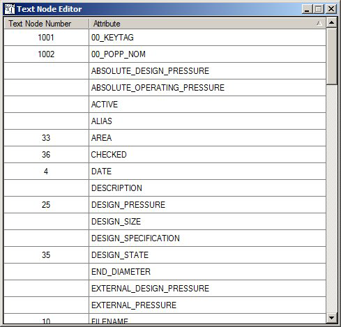
36,checked
63,UNIT_NAME
64,STYLE
1001,00_KEYTAG
1002,00_POPP_NOM
Now when the Text Node Editor is started the added drawing attributes will be shown and can be placed on the isometric:
DATE function
DATE (<style>, <format>)
Where:
   <style>   0 for US style (e.g. 12/25/2013),
             1 for European style (25/12/2013)
   <format>  examples shown for US style (January 2 2013)
             0              1-2-13
             1              01-02-13
             2              1-2-2013
             3              01-02-2013
             4              1/2/13
             5              01/02/13
             6              1/2/2013
             7              01/02/2013
             8              20130102
- The definition file is read first
- The drawing attributes already present from the design system are read second. Drawing attributes will not override a drawing attribute definition.
- The expressions are evaluated. The order of evaluation is determined by the software.
- The results are read back and put into the drawing attribute (MicroStation) tag.
Errors are reported in a user friendly manner, the Query function in particular.
Circular references will be detected and the drawing attribute will be set to the value "r;FAILED"
myAttr = $(myAttr)
#-----------------------------------------------------------------------------
# An example extended drawing attribute definition file
#-----------------------------------------------------------------------------
# Defined a fully qualified DSN (data source name;user;passwd)
  IE_DSN  = PSDS 8.9 SI Example;proj;none
# Example new simple drawing attribute CODE
  code    = 2605-2
# A few examples of SQL queries
#  - please note that LINENUMBER is assumed to be a drawing attribute supplied
#    by the piping system
  var1 = DBQUERY ($(IE_DSN), CREATE TABLE isometric (LineNumber varchar(255)))
  var2 = DBQUERY ($(IE_DSN), INSERT INTO isometric VALUES ('$(LINENUMBER)'))
  var3 = DBQUERY ($(IE_DSN), select description from code_desc where code='$(code)')
# Some queries that will fail + messages produced
# - Unable to open statement handle for ODBC data source: xx
  var10 = DBQUERY (xx, )
# - MSG = [Microsoft][ODBC Microsoft Access Driver] Invalid SQL statement;
     expected 'DELETE', 'INSERT', 'PROCEDURE', 'SELECT', or 'UPDATE'.
  var11 = DBQUERY ($(IE_DSN), incorrect sql statement)
# - expression DBQUERY (: no matching close brace found for function: DBQUERY
  var12 = DBQUERY (